
Knowledge
[Types and Features] Stepping Motor — Operating Principles and Types


A stepping motor is a type of control motor that rotates by a fixed angle each time the energized phase is switched, moving step by step like a clock. It enables position control without sensors. Stepping motors are also known as pulse motors, step motors, or stepper motors.
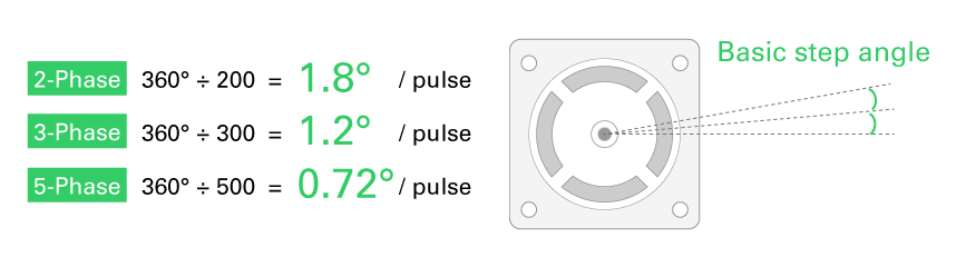
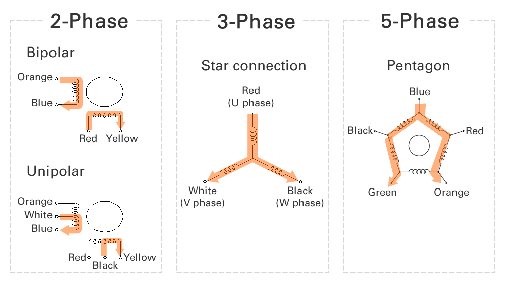
Stepping motors are classified into 2-phase, 3-phase, and 5-phase types according to their structure.
The angle through which a stepping motor rotates with a single pulse is called the basic step angle. A smaller basic step angle allows smoother motion and higher positioning accuracy.
A driver is required to operate a stepping motor. When designing a driver, it is important to note that for 2-phase stepping motors, the drive circuit differs depending on whether bipolar drive or unipolar drive is used. For 3-phase and 5-phase stepping motors, a driver capable of supplying bidirectional current is required.
In addition, 2-phase and 3-phase stepping motors have relatively simple winding structures, which allow motors from different manufacturers to be driven using the same drive circuit. However, 5-phase stepping motors have more complex winding structures, and the combinations and sequence of phases used to rotate the motor are not standardized. Therefore, when using a 5-phase stepping motor, careful attention must be paid to the selection of a compatible driver.
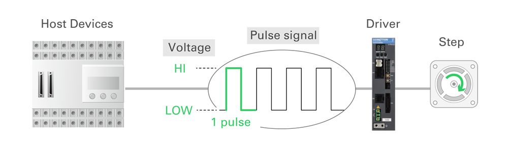
First, regarding pulse command signals, these are electrical signals in which the voltage repeatedly switches between ON and OFF (HI/LOW). One cycle of HI and LOW is counted as one pulse.
Pulse signals are input to the driver from an upper-level controller, and the number of pulses determines the motor’s rotational angle.
Speed Control of Stepping Motors
The rotational speed of a stepping motor is controlled by the density of pulse signals. When one pulse corresponds to one basic step angle, sending 10 pulses per second results in a larger rotational angle in one second than sending 1 pulse per second. Therefore, a higher pulse frequency leads to a higher rotational speed.
Position Control of Stepping Motors
In recent years, many drivers have adopted microstepping control, which finely adjusts the amount of current supplied to each phase. This makes it possible to position the motor at angles smaller than the basic step angle. As a result, finer position control can be achieved.
Advantage 1: Simple Control
Stepping motors are easy to operate because they only require ON/OFF control of the driver transistors. The rotational speed can be adjusted by changing the ON/OFF timing.
Advantage 2: Simplified System Design
Stepping motors can be easily controlled using input pulse signals and their frequency, eliminating the need for complex controllers. In addition, as stepping motors can control position and speed without sensors, the overall system can be simplified.
Advantage 3: Cost-Effective System Design
A stepping motor system can be built at low cost because the driver is simple, no sensors are required, and a complex controller is not required.
Advantage 4: Stable Holding at Stop
Stepping motors are stopped by magnetic force, which generates a holding force known as holding torque. This allows the motor to remain stably stopped when it is not rotating.
Although stepping motors are not usually visible in our daily lives, they play an important role inside many types of equipment that support everyday activities. Where are they actually used? Typical applications include the following.
For more detailed information, please refer to "What is a stepping motor? Applications and usage examples of stepping motors."
Precaution 1: Loss of Synchronization (Step-Out)
Stepping motors do not require sensors; however, because the actual position is not monitored, it is not possible to detect when the motor fails to follow commands and loses synchronization (step-out). Compared with servo motors using closed-loop control, stepping motors are more dependent on proper operating conditions.
Precaution 2: Heat Generation
Stepping motors generate holding torque even when stopped, which means current continues to flow and can result in heat generation.
Precaution 3: Vibration During Motion
Stepping motors rotate in fixed angular increments and move step by step like climbing stairs, which can result in vibration during motion.
| Stepping Motors | Servo Motors | |||
| Control | Open-Loop | Closed-Loop | ||
| Torque | Without Sensor | Always generates a constant holding torque in the direction that prevents the motor from rotating. | Motor Current Sensor | Controls motor current in the rotating direction to generate the commanded torque. |
| Rotational Speed | Without Sensor | Rotates at a speed synchronized with the input pulse frequency. If it cannot synchronize, step loss occurs. | Motor Speed Sensor | Moves while monitoring motor speed so that it rotates at the commanded speed. |
| Position (Angle) | Without Sensor | Moves by the number of input pulses. If the motion cannot keep up, step loss occurs. | Motor Position Sensor | Moves while monitoring motor position to reach the commanded target position. |
| Features | Inexpensive and easy to use; high torque at low speeds | More expensive but equipped with various functions; high torque even at high speeds | ||
| Friction | Accurate and quick positioning is possible even with large friction. | Precise positioning is possible, but large friction may increase positioning time. | ||
| Resonance / Vibration | Large speed ripple; resonance cannot be suppressed by the motor itself. | Speed ripple and resonance can be suppressed by driver functions. | ||
| Inertia Ratio | Motor cannot be controlled if load inertia is large. | Motor can be controlled even with a large inertia ratio. | ||
| Best Suited Application |
Holding the same position. | Stable rotation (low vibration and noise). | ||
| Low-speed, short-distance start-stop motion. | High-speed, high-acceleration start-stop motion. | |||
| Light machining operations. | Precision machining and heavy machining operations. | |||
release date:


Aiming to be the world's No. 1 in manufacturing
Technical capabilities that enable advanced customization

Our 100th anniversary soon

Global Network