Knowledge
[Fan Basics] Lesson 7


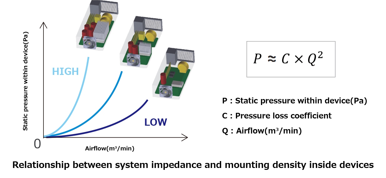
"Airflow resistance," also referred to as "system impedance," describes how difficult it is for air to flow through a device. Changing the fan typically doesn’t significantly affect this resistance unless the number or arrangement of internal components is modified.
Airflow resistance is generally modeled as a quadratic curve, meaning it increases with the square of the airflow. When resistance is low and air flows easily, the curve becomes flatter along the X-axis. When resistance is high and airflow is restricted, the curve rises more steeply along the Y-axis.
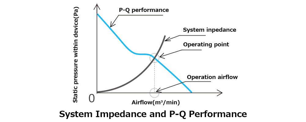
By identifying the point where the device’s airflow resistance curve intersects with the fan’s airflow–static pressure characteristics, we can determine whether the fan is suitable for the system. This intersection is known as the fan’s “operating point,” and the airflow at this point is referred to as the “operating airflow.”

Airflow resistance can be calculated using formulas. However, measurement equipment is required in either case, as this method also involves measuring the fan’s operating airflow. To precisely evaluate fan performance, a multi-nozzle double chamber measuring device is typically used.
In this method, the pressure difference between chambers A and B is used to calculate the air velocity at the nozzle. The airflow is then determined by multiplying that velocity by the nozzle’s cross-sectional area. By using nozzles with different sizes depending on the airflow range, accurate measurements can be made for various conditions.
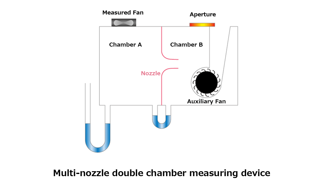
Generally, double chamber measurement devices are large in size and are typically stationary units. As such, the device to be measured must be transported to the location where the double chamber system is installed.
SANYO DENKI has developed the “Airflow Tester,” a portable airflow measurement device that makes testing easier and more flexible.
Because it uses the same multi-nozzle double chamber method, this device makes it easy to measure airflow resistance and operating airflow with high accuracy. It’s a compact solution that still provides high-precision results, even outside of a lab environment.
Using the Airflow Tester to measure airflow resistance can assist in the efficient design of enclosures with proper thermal management.
| Double chamber measuring device | Airflow Tester | |
| mass | Approximately 600kg | Approx. 6kg |
| Size (mm) | 1000×1000×6000 | 250×250×600 |
| Air volume (m3 /min) | 0.05-20 | 0.2-8.0 |
| Static pressure (Pa) | 0-2000 | 0-1000 |
| Measurement method | Double chamber system | |
| Measurable items | Operating air volume, ventilation resistance, air volume-static pressure characteristics | |
| Air flow measurement accuracy | ±2% | ±7% |
Supervised by: SANYO DENKI CO., LTD. Cooling System Design Department
Update date: /release date:
Aiming to be the world's No. 1 in manufacturing
Technical capabilities that enable advanced customization

Our 100th anniversary soon

Global Network