Knowledge
[Fan types and features] Counter Rotating Fan


In the previous section, we introduced axial flow fans. In this section, we’ll explain a special type of axial flow fan called the counter rotating fan.
A counter-rotating fan is a type of axial fan consisting of two fan units arranged in series. The front unit draws air in, while the rear unit discharges it. These two fans rotate in opposite directions. For instance, if the front fan rotates counterclockwise, the rear fan rotates clockwise.
Although the structure may appear to be just two axial fans placed in series, using two identical axial fans in this way does not deliver the same performance as a counter rotating fan.
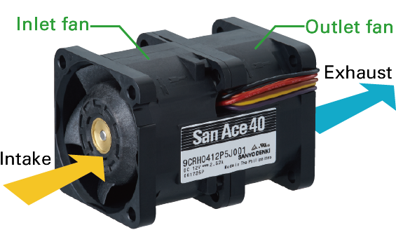
Figure 1: Structure of Counter Rotating Fan
When two axial fans rotating in the same direction are connected in series, the rear fan intensifies the swirling airflow generated by the front fan. This causes the airflow to become more turbulent and less directed.
In contrast, with a counter rotating fan, the rear blades rotate in the opposite direction, which weakens the swirling airflow generated by the front fan. This results in a more streamlined, straight flow of air.
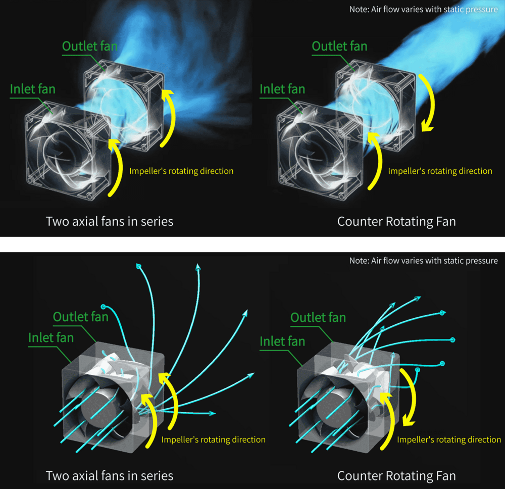
▲Figure 2: Image of air flow
The performance of a counter-rotating fan largely depends on the configuration of its front and rear blades.
SANYO DENKI’s counter rotating fans are designed with careful consideration of airflow, static pressure, noise, and lifespan to achieve optimal performance.
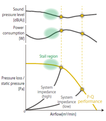
Figure 3: Example of ventilation resistance and air volume - static pressure characteristics
Because the front and rear rotors of a counter rotating fan rotate in opposite directions, the airflow inside the fan changes significantly. This leads to much higher static pressure compared to axial fans that deliver the same maximum airflow. Previously, we learned that in conventional fans, there is a region where airflow over the blade surface becomes unstable, alternating between smooth flow and swirling motion. This phenomenon, called rotating stall, typically occurs near the middle of the P-Q curve. However, in counter rotating fans, the rotating stall region appears within the range where the P-Q curve remains relatively flat.
Figure 3: Example of ventilation resistance and air volume - static pressure characteristics
Since the rotating stall region in a counter rotating fan appears toward the left side of the P-Q curve, the optimal operating range is wider. This enables the fan to deliver airflow effectively even in systems with high ventilation resistance, without being affected by nearby obstacles.
This means that counter rotating fans are well suited for compact, high-density devices and for spot cooling applications where air needs to be directed straight onto the object being cooled. They can also be used effectively in situations where airflow must reach over a long distance.
Here are some case studies.
This concludes our overview of counter rotating fans.
SANYO DENKI’s fan lineup includes counter rotating fans and other models tailored to meet the specific needs of customers' equipment designs.
Supervised by: SANYO DENKI CO., LTD. Cooling System Design Department
release date:
Aiming to be the world's No. 1 in manufacturing
Technical capabilities that enable advanced customization

Our 100th anniversary soon

Global Network